The previous blog post was about Voronoi and Delaunay graphs, how I used them for procedurally generating maps in 2010, and how I want to use them differently for my next procedural map generator. I use these unstructured grids[2] instead of regular grids to add variety and interestingness to the maps.
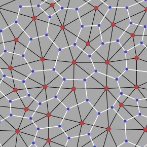
I need a way to represent this graph, including many of the relationships listed here[3], except adapted to this dual graph:
- Blue point → one triangle it's contained in
- Blue point → three polygons it is a corner of
- Blue point → three white edges it connects to
- Red point → one polygon it's contained in
- Red point → many triangles it's a corner of
- Red point → many black edges it connects to
- Black/white edge → two blue endpoints
- Black/white edge → two red endpoints
Back in 2010, I represented each of these as a separately allocated array. I didn't know any better. The people who work in computational geometry have much better ways to represent these kinds of "dual graphs". The structure of the graph is the same whether I'm using Voronoi (circumcentral coordinates) or the graphs I ended up with (barycentric / centroid coordinates). I only need to represent one half of the dual graph, since the parts correspond:
- Blue points correspond to black triangles
- Black edges correspond to white edges
- Red points correspond to white polygons
There are many possible representations, including quad edges, split edges, winged edges, half edges, and others. I decided to use the “half edge” data structure for this project. Read about them on flipcode.com[4] or martindevans.me[5]. I read several papers and watched some talks to learn what's on this page, and wrote it down here as a reference for myself.
Structure#
Let's focus on the triangles. The red points are the vertices. They come from the seed points, so I'm going to call give them an “s-index”, which also identifies the white polygons. Let's give the triangles a “t-index”, which also identifies the blue points. Edges will be represented as directed (“half”) edges, each with an “e-index”, which also lets us construct the white edges.
How will I represent this graph? For the structure I need the relationships between seeds and edges:
-
edges: edges → seeds that are the start point of the edge. For example edge e2 is s{{graph.s_begin(2)}} → s{{graph.s_end(2)}} soedges[e2] = s{{graph.edges[2]}}(where the edge starts). -
opposites: edges → edges that are the same location, opposite direction. For example edge e2 is s{{graph.s_begin(2)}} → s{{graph.s_end(2)}} and e{{graph.opposites[2]}} is s{{graph.s_begin(graph.opposites[2])}} → s{{graph.s_end(graph.opposites[2])}} soopposites[e2] = e{{graph.opposites[2]}}. Similarly,opposites[e{{graph.opposites[2]}}] = e2. Some edges won't have opposites. -
starts: seeds → edges : an edge that starts with this seed. For example, seed s2 has edges e2 and e3 coming from it, so either of those can go into the array. For interior seed points it doesn't matter whether which. For exterior seed points we want the “leftmost” edge, sostarts[s2] = e2.
I also have two arrays for the geometry of the graph:
-
s_coords[s]is the x,y for each red point s -
t_coords[t]is the x,y for each blue point t
Most of the procedural map generation steps will work with the structure; I will use the geometry when I'm drawing the map.
Example#
There are exactly three edges for each triangle. That means I can work with edges most of the time: t_index(e_index) = int(e_index/3). Here's the edges mapping for the above diagram:
t{{t_index(e)}}: e{{e}} → s{{graph.edges[e]}}
Here's the opposites mapping:
t{{t_index(e)}}: e{{e}} → e{{graph.opposites[e]}}---
And here's the starts mapping:
s{{s}} → e{{graph.starts[s]}}
Since the s-indices and e-indices are small integers, these mappings can be stored as a dense array of integers. This is memory efficient and also cache friendly. For example, opposites[e2] = e5 will be stored as opposites[2] = 5. If there's no opposite, store -1.
Bonus: in GL_TRIANGLES indexed mode drawing, edges will be the indices and s_coords will be the vertices.
Operations#
Try mousing over or tapping any red or blue point:
- Blue point (t) to one triangle (e1 e2 e3) it's contained in: {{ highlight }} → {{ format_e_array(graph.e_triangle(highlightId)) }}
3*t+i for 0 ≤ i < 3 - Blue point (t) to three polygons (s1 s2 s3) it is a corner of: {{ highlight }} → {{ format_s_array(graph.s_triangle(highlightId)) }}
edges[3*t+i] for 0 ≤ i < 3 - Blue point (t) to three blue points it connects to: {{ highlight }} → {{ format_t_array(graph.t_neighbors(highlightId)) }}
t_index(opposites[3*t+i]) for 0 ≤ i < 3(*) - Red point (s) to outgoing edges (e1 e2 …): {{ highlight }} → {{ format_e_array(graph.e_loop(highlightId)) }}
e for e ∈ e_loop(s) - Red point (s) to incoming edges (e1 e2 …): {{ highlight }} → {{ format_e_array(graph.e_loop(highlightId).map(PREV)) }}
PREV(e) for e ∈ e_loop(s) - Red point (s) to red points (s1 s2 …) it connects to (**): {{ highlight }} → {{ format_s_array(graph.s_neighbors(highlightId)) }}
s_end(e) for e ∈ e_loop(s) - Red point (s) to many triangles (t1 t2 …) it's a corner of: {{ highlight }} → {{ format_t_array(graph.t_polygon(highlightId)) }}
t_index(e) for e ∈ e_loop(s) - Half edge (e) to white edge's two blue endpoints: (no demo)
t_index(e), t_index(opposites[e])(*) - Half edge (e) to black edge's two red endpoints: (no demo)
edges[e], edges[NEXT(e)]
    function PREV(e) { return (e % 3 == 0) ? e+2 : e-1; }
    function NEXT(e) { return (e % 3 == 2) ? e-2 : e+1; }
    function e_loop(s) {
        const e0 = starts[s];
        let e = e0, e1 = -1;
        do {
            yield e;
            e1 = opposites[e];
            e = NEXT(e1);
        } while (e1 >= 0 && e != e0);
    }
(*) There are special cases we have to handle at the exterior edges because they don't have opposites.
(**) This algorithm as described doesn't actually work for exterior red points. See the next section for a way to fix it.
Although there are a lot of operations listed above, they can be put into two basic patterns:
-
Circulate around a blue point using the 3 indices for a triangle's black edges, using the
NEXT(counterclockwise) orPREV(clockwise) functions. -
Circulate around a red point using the
e_loopfunction. This will visit (clockwise) each black edge connected to the red point.
I'm still looking for good names for these functions; I should look at libraries like jCAE[6] and CGAL[7] and OpenMesh[8]. I don't yet know whether I want to think about blue and red points, with the triangles and polygons secondary, or if I want to think about triangles and (red) vertices, with the blue points and polygons secondary.
Special cases#
In the previous section there are some functions marked with (*) where we might walk outside the exterior and get a null (-1). Exterior seeds also complicate things for the starts[] array, since we have to treat interior and exterior seeds differently. The red point to red points it connects to function is missing one red point if you start with an exterior seed. Ugh! Most half edges have an opposite but some don't, so you have to be careful, and sometimes you can't even get the information you want.
With grids there's a trick to avoid some of these situations: add an extra row and column to the outer boundaries of the map. When you try to access array[x-1][y] you access a special boundary grid location that is filled in with default values.
There's a similar trick for polygon meshs which I found in several papers: make new triangles around the outer boundary of the mesh. It goes by different names: "outside" vertex, "infinity" vertex, "ghost" vertex. If there are N half edges that are missing an opposite:
- Create N ghost triangles. These will be on the outer edges of the map.
- Create 3*N ghost edges. Of each three, one will fill in the missing half edge. The other two are used to build the triangles.
- Create 1 ghost seed. This seed will be outside the map area, and is the third vertex for the added triangles.
Think of this putting an extra seed on the back of your map, and then putting extra triangles around the boundary of your map that wrap around to the back.
Ok, so now we've replaced all the checks for -1 by checks for things that go to the back of the map. Isn't it still annoying? Yes, but it's less annoying.
- The
starts[]array is simpler to calculate. No need to find the "leftmost" point. It's a 3 line loop instead of 22 lines to build an index and travrese edges. - The red point to red point function returns all the red points (but may sometimes return the ghost seed). It works on all the exterior points now instead of returning the wrong answer.
- All half edges have an opposite (but some are ghosts).
- The loop around edges (
e_loop) no longer gets stuck at a missing half edge. Sometimes we'll need to filter out the ghosts. - The ghost seed's neighbors are the boundary of the map. This is a useful thing to know (for example, to fill the boundary with water), and now I don't have to keep track of it separately.
Since all the extra edges are added to the end of the existing edges, it's easy to know whether it's a ghost edge: e > numSolidEdges. Similarly, the ghost seed is added to the end of the seed array, so it's easy to identify.
Filtering out all the ghosts seems annoying. But so does dealing with nulls / -1s. Do I need to filter out ghost structures at every step? No, I think most of the map generation code won't care which structures are solid and which are ghost. I only have to filter the ghosts at the very end, when drawing the map. I think that's a win.
More reading#
I'm a computational graphics newbie. I'm learning about this stuff while working on the map generator project. I don't know all the different mesh formats and which works best for my application, but this seems like it'll be pretty good. Here's some reading:
- Jerry Yin and Jeffrey Goh have an interactive guide to half-edge data structures[9] that I wish I had seen before I wrote this page. But it didn't exist until 2019, and I wrote my page in 2017.
- Comments on reddit/proceduralgeneration[10], Hacker News[11]
- Flipcode's introduction to half edges[12] and Martin Evans's introduction to half edges[13] are both worth a read.
- There's an optimized implementation for C++ described in Gino van den Bergen's GDC 2017 talk, “B-rep for Triangle Meshes” (read the slides[14], or watch the video[15] if you have GDC Vault access).
- Shewchuk's Lecture notes on Delaunay Mesh Generation[16] [PDF] is fantastic. Chapter 1 is a nice overview and history of mesh generation, including varying triangle density, non-rectangular constraints, triangle quality metrics. Chapter 2 covers Delaunay triangulation, including the connection with convex hulls, properties of triangulation, and several algorithms. Chapter 3 covers algorithms and data structures, including the idea of filling in all the unpaired half edges with a "ghost" triangle. It also mentions that the first Delaunay algorithm was from a biologist who discovered the structure of graphite and was praised by Arthur C Clarke for his sci fi stories. Chapter 6 covers refinement, which adds extra vertices to make the triangles nicer. I didn't read the entirety of these chapters, and I skipped chapters 4, 5, 7 entirely.
- Ruppert's Algorithm[17] and Chew's second algorithm[18] add vertices to make the Delaunay triangulation better.
- Data Structures for Multiresolution Representation of Unstructured Meshes[19] [PDF] uses a lath data structure for half edge, split edge, and corner representations of dual meshes. The paper also includes great diagrams showing how the dual circulation algorithms work.
- Primitives for the manipulation of general subdivisions and the computation of Voronoi[20] covers the quad edge data structure; see this note[21] about the implementation (thanks to modalduality on HN[22])
- Is all of this related to homology[23]? Not sure yet.
- Half edge data structure considered harmful[24] says half edges are error prone to construct, and other data structures are better. In my case, Delaunator produces the half edge structure so I'm not constructing them, but this could come up if you're modifying meshes.
I usually use D3-voronoi[25] for my projects but this time I'm trying the Delaunator library[26] to construct the half edge structure. Not only is it very fast, it returns information in exactly the format I wanted for the edges and opposites arrays. Nice. I'll have to extend these arrays if I want to use the “infinity” point to reduce special case code.