#+title: Terrain shader experiments
#+date: <2017-07-28>
#+begin_export html
#+end_export
For the [[http://www-cs-students.stanford.edu/~amitp/game-programming/polygon-map-generation/][polygon map generator]] project back in 2010 I used Flash's 2D vector graphics, which are similar in capability to HTML5's Canvas vector graphics: lines of varying widths, polygons with fill and outline, bezier and arc curves. I wanted to explore what I might be able to do with GL shaders. With GL I primarily get triangles. There are lines, but line width other than 1 isn't guaranteed to be supported in WebGL. There are no curves; I'd have to break things down into line segments, which I render as quads, which are rendered as two triangles. On the other hand, GL gives me three-point gradients and lots of other potentially useful features. In order to evaluate the capabilities /for abstract map rendering/ (not 3d terrain), I tried some things, which I describe on this page.
The main idea is to pass the /barycentric coordinates/ into the fragment shader, along with the three vertex colors /separately/. I can then do something other than the standard three-point gradient. This idea seemed obvious to me so I checked forums, stackoverflow, etc., and found that many other people have had the same idea, often for making wireframes. So that's a good sign that I'm not barking up the wrong tree.
* Barycentric coordinates
:PROPERTIES:
:CUSTOM_ID: barycentric-coordinates
:END:
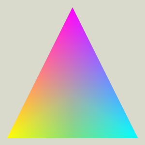
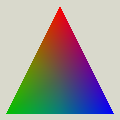
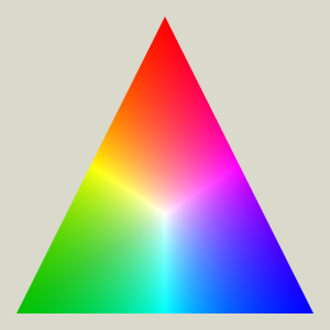
Let's start with the standard OpenGL triangle example:
#+begin_export html
#+end_export
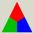
What's going on here? If you pass in three colors at the three vertices, OpenGL will interpolate the colors smoothly.
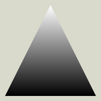
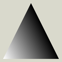
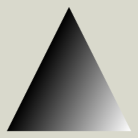
The [[https://www.scratchapixel.com/lessons/3d-basic-rendering/ray-tracing-rendering-a-triangle/barycentric-coordinates.html][barycentric coordinates]] tell you how much of each color is being mixed at any position in the triangle. The red and magenta corners are (1, 0, 0); the green and yellow corners are (0, 1, 0); the blue and cyan corners are (0, 0, 1). The center of the triangle is (1/3, 1/3, 1/3). The midpoints are (1/2, 1/2, 0), (0, 1/2, 1/2), and (1/2, 0, 1/2). Here are the three separate coordinates:
#+begin_export html
#+end_export
I want to use the barycentric coordinates to make other effects, which would be useful for my map generator's renderer.
* Min and Max
:PROPERTIES:
:CUSTOM_ID: min-and-max
:END:
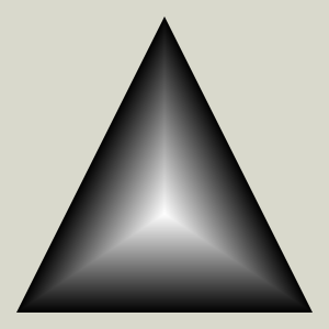
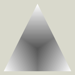
Instead of interpolating, I can color based on the min or max coordinate:
#+begin_export html
#+end_export
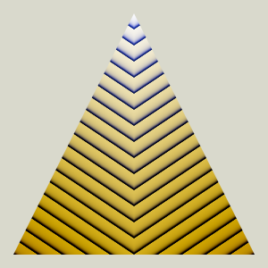
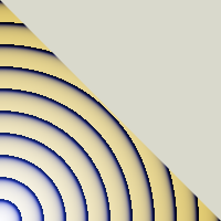
I'm going to draw them as /distance fields/ instead, because that'll come in handy later when we want to make stripes:
#+begin_export html
#+end_export
I can use them like this:
#+begin_export html
#+end_export
The /min/ diagram lets me put a color on the points closest to an edge. In my map generator, that'll be mountain ridges. The /max/ diagram lets me put a color on the points closest to a vertex. In my map generator, that'll be biome colors.
* Edges and stripes
:PROPERTIES:
:CUSTOM_ID: edges-and-stripes
:END:
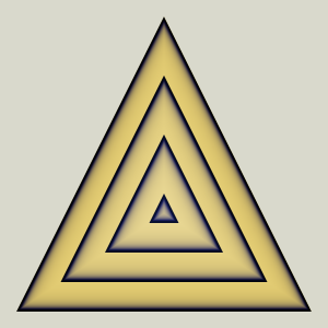
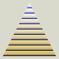
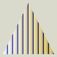
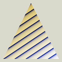
If I test for the barycentric coordinate being between two values, I can make a stripe, sometimes at the edge of the triangle. A stripe in the middle of the triangle could be useful to draw borders around biomes.
#+begin_export html
#+end_export
Some people use stripes of the min or max of the coordinates for wireframes.
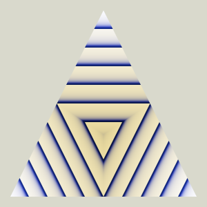
The /sum/ of two coordinates looks the same an individual coordinate.
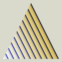
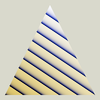
The /difference/ of two coordinates gives me stripes different from a single coordinate:
#+begin_export html
#+end_export
The /product/ of two coordinates does not look useful:
#+begin_export html
#+end_export
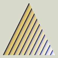
The /ratio/ of two coordinates might be useful:
#+begin_export html
#+end_export
* Blended max
:PROPERTIES:
:CUSTOM_ID: blended-max
:END:
In between regular linear interpolation and max you can get other blends by raising the weight to a power. In the limit, at infinity, it's the same as max.
#+begin_export html
#+end_export
This will give some options for blended biome borders. However, /high exponents don't work well across platforms/, probably because raising things to high exponents loses precision somewhere.
There are probably lots of other useful blending approaches. I should look at all the functions [[https://iquilezles.org/articles/functions/][from Inigo Quilez]].
* Corners
:PROPERTIES:
:CUSTOM_ID: corners
:END:
I can use a /biased max/, max(r + w, g, b), to shift the red region in and out:
#+begin_export html
#+end_export
Subtracting these, I can make any of these stripes:
#+begin_export html
#+end_export
This seems potentially useful for rivers or roads, or borders between biomes. I also tried the /weighted max/, max(w * r, g, b), but the stripe wasn't uniform width. (However the stripes won't be uniform width anyway once the triangles aren't equilateral, so maybe it doesn't matter that much…)
I think it may be simpler to build this by taking the union and intersection of stripes. I haven't tried that yet.
* Noisy borders
:PROPERTIES:
:CUSTOM_ID: noisy-borders
:END:
Use the biased max, but use a noise parameter for the bias for all three channels. This could produce more interesting biome boundaries.
#+begin_export html
#+end_export
For this demo I'm using the GLSL noise functions from Morgan McGuire, BSD licensed, found [[https://www.shadertoy.com/view/4dS3Wd][in this shadertoy]]. Another place you can get GLSL noise functions is [[https://github.com/ashima/webgl-noise/][the webgl-noise library]], MIT licensed.
* Curved paths
:PROPERTIES:
:CUSTOM_ID: curved-paths
:END:
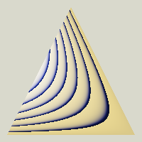
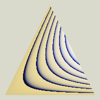
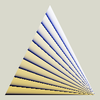
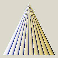
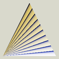
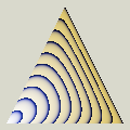
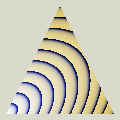
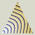
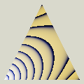
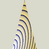
I'd like to have curved paths, especially for rivers. Let's take two straight segments and /blend them together/ with different distance functions:
#+begin_export html
#+end_export
Cool patterns. Are they useful?
** Tiling
:PROPERTIES:
:CUSTOM_ID: tiling
:END:
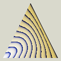
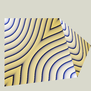
The curved paths look interesting but they need to tile across triangles of various shapes and sizes. The best matches were function 4 and function 6, and the other styles were worse than these:
#+begin_export html
#+end_export
Even with these, the lines don't meet properly at the edges. Why? Although the /midpoints/ match, the /slopes/ do not. That's because the slope depends on the shape of the triangle. Implementing the curve in barycentric coordinates ignores the shape.
** Properties
:PROPERTIES:
:CUSTOM_ID: properties
:END:
What do I need here?
1. Approximately constant width
2. Lines perpendicular to the edges
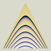
Both are hard, but the harder problem is requirement (2). Here's distance function 6 drawn with several different triangle shapes:
#+begin_export html
#+end_export
It's perpendicular to the edges in the first shape but not the second or third. Making the line perpendicular to the edge /depends on the triangle geometry/ so there isn't going to be a single pattern here that works across all triangles.
I'm going to move on, and return to this problem later. It's possible I can find some other simpler approach and not deal with these in shaders.
** TODO Arcs and splines
I think I need to construct an arc or spline for each triangle, and write a shader that takes extra parameters that control the shape.
[[https://developer.nvidia.com/gpugems/gpugems3/part-iv-image-effects/chapter-25-rendering-vector-art-gpu][GPU Gems chapter 25]] is about splines in shaders. I should read that.
* Bonus: Prismatic colors
:PROPERTIES:
:CUSTOM_ID: bonus-prismatic-colors
:END:
The cool-looking [[https://psgraphics.blogspot.com/2015/10/prismatic-color-model.html][prismatic color model]] uses barycentric coordinates divided by the max of them:
#+begin_export html
#+end_export
See [[https://www.semanticscholar.org/paper/THE-PRISMATIC-COLOR-SPACE-FOR-RGB-COMPUTATIONS-Hart/106512fd3c1186f9e8fa6a141a20d1a182429e01][the paper about the prismatic color space]] ([[href:mirror/THE PRISMATIC COLOR SPACE FOR RGB COMPUTATIONS.pdf][mirror]]). This isn't related to my map generation project but I thought it looked cool and wanted to share.
* Conclusion
:PROPERTIES:
:CUSTOM_ID: conclusion
:END:
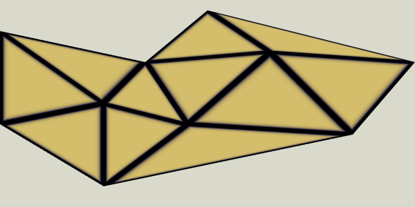
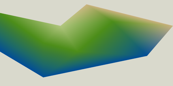
Here are some triangles that might be in the delaunay triangulation for a map:
#+begin_export html
#+end_export
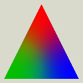
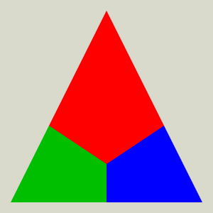
If I assign a biome at each /vertex/, I can draw the biomes with smooth transitions…
#+begin_export html
#+end_export
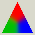
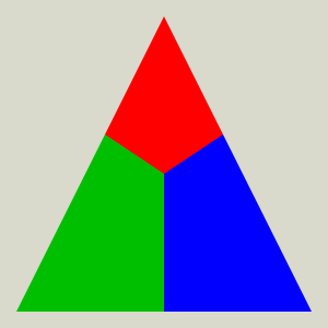
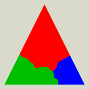
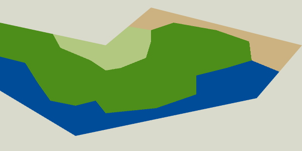
…but for some game maps I may want to make the transitions more pronounced, which I can do with soft transitions…
#+begin_export html
#+end_export
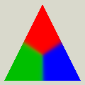
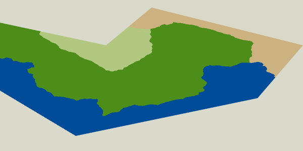
…or with hard transitions…
#+begin_export html
#+end_export
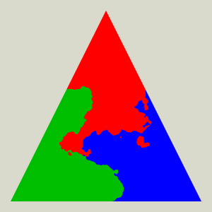
…or with noisy transitions…
#+begin_export html
#+end_export
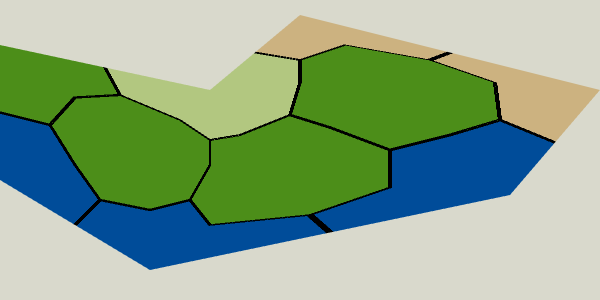
…and/or with border lines:
#+begin_export html
#+end_export
It will be some more work to make the border lines have constant width. I need to re-read [[https://iquilezles.org/articles/voronoilines/][IQ's page on voronoi lines]].
Overall, this is kind of cool, and it works nicely for biomes. The noisy transitions in particular are much cheaper this way than inserting hundreds of vertices into each polygon. I'm not sure if I'll end up using it though. It's pretty early in our game's development and we haven't decided everything about the maps.
In my code I had to make one copy of each vertex per triangle (instead of sharing as we normally would want to do) so that I could pass in a different barycentric value for each triangle. Newer GPUs have a feature called [[https://wunkolo.github.io/post/2022/07/gl_ext_fragment_shader_barycentric-wireframe/][GL_EXT_fragment_shader_barycentric]] that will include these without you having to duplicate vertices, but I don't expect these will be available in WebGL anytime soon.
Source code for making the diagrams: href:terrain-shader-experiments.js
#+begin_export html
Created 25 Jul 2017 with Emacs org-mode (source of this page);
Last modified: 03 Jul 2025
#+end_export