I wanted to try animating some of the objects from these sketches.
truck {{truckPosition.toFixed(0)}}
I focused on the roads for this miniproject. I've never worked with smooth vehicle-on-track movement before. I've used grid movement, or smooth movement not on a grid. So this was something I had to stop and think about.
Let's start with movement on a straight line. I decided each tile would be 1⨉1. Since roads are all one-way, positions along a route can be represented as numbers from 0 to the length of the route. Routes are loops so position = length is equivalent to position = 0.
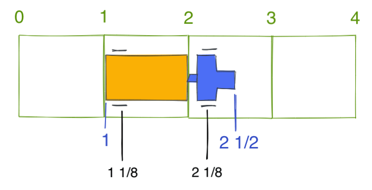
A truck has a position, but occupies a range, not only a single position. This truck is positioned at 2, so its container occupies the range 1:2. The vehicle occupies the range 1:2½. The wheels are treated as positions, so these wheels are at postiion 1⅛ and 2⅛.
Collision options:
- I could test for collision on position ranges. This means one truck 1:2½ can be behind another truck 2½:4.
- I could test for collision on tiles. This means the truck 1:2½ occupies tiles 1,2 and will not allow another truck 2½:4 which wants to occupy tiles 2,3. Instead, the second truck will have to be 3:4½, to occupy tiles 3,4.
- I could test geometrically, against all other vehicles moving into a space. This would allow truck 1:2½ to be behind truck 2½:4 because their rectangles don't intersect.
It seems like position ranges are are easy and flexible, but position coordinates only make sense within one route loop, and I want to have multiple overlapping and intersecting route loops. This means I need to convert from the local coordinates (within a route) to world coordinates, and I can't use option 1. Of options 2 and 3, I think the geometric approach is more flexible but also more work, especially on curves. I could be wrong. I'm going to use option 2 (tiles) for now and then revisit this. There are enough other problems for me to work on that I want the simplest thing that could possibly work (if you are not sure what to do yet)[1].
Its possible the turning truck may have some corners stick outside the tile, which means solution 3 would be more accurate than solution 2.
Acceleration and deceleration: I want a truck to stop if it think there may be something in the way up ahead. I think I can add a lookahead range, 2½:3½ here:
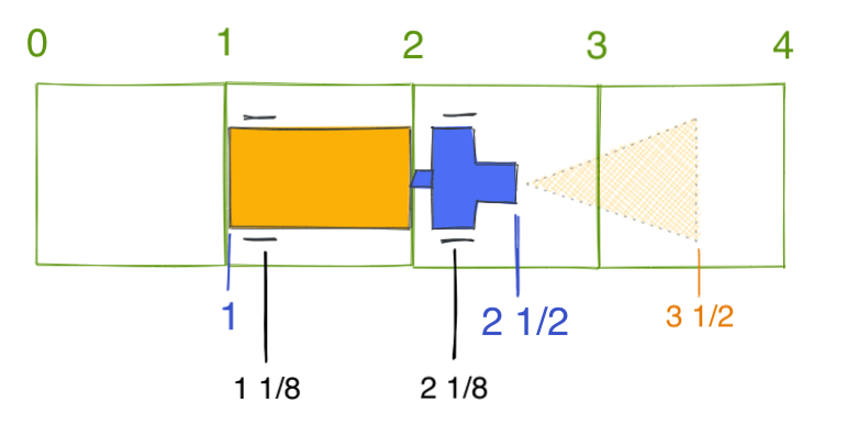
Then the truck can start decelerating if the lookahead range is occupied. But how fast should it decelerate? I will need to think about this more. (The lookahead range seems like it should depend on the current speed)
For curved roads, the truck's wheels need to be centered on the road, and then the rest of the truck is rotated to fit.
What data do I need? I can't answer that until I know what I'm going to do with it. I made a list:
- What is the SVG path to draw the route?
- What is the length of the route?
- Given 0 ≤ position < length, what is the x,y position along the route?
- Given a vehicle, where should it be drawn?
- Given a vehicle, how much should it be rotated?
- Given a vehicle, what tiles does it occupy?
- Given a vehicle, what tiles is it going to occupy if it doesn't stop? (related: lookahead)
I decided these might be useful:
- startedge[i]: GridEdge
- the ith edge
- endedge[i]: GridEdge
- the i+1th edge
- command[i]: Command
- how to drive to the next edge
- tile[i]: GridTile
- the tile between edge i and edge i+1
- length[i]: number
- the length of the path between edge i and edge i+1
- startposition[i]: number
- the length of the path between edge 0 and edge i
- endposition[i]: number
- the length of the path between edge 0 and edge i+1
Of these, I think startedge[0], command[…] are fundamental, and everything else can be computed from those. The command tells us how to get to the next edge and its length. The edge tells us what the next tile is. The position values are the sum of the length values.
Example: if I want to know which tiles are occupied by a vehicle at position p=3½, I can look up the vehicle range, which is p-1:p+½, so that's 2½:4. I need to turn these positions into edge numbers, so I look through the list to find edge i with startposition[i] ≤ 2½ < endposition[i] and similarly an edge j that contains position 4. The tiles occupied will be tile[i], tile[i+1], …, tile[j-1].
I decided I would use turtle graphics commands to define the commands. F 3 R F 2 would mean forwards 3 tiles, turn right, forwards 2 tiles. Since I'm making an animation and not a simulation, I'm going to write these by hand, and not worry about an editor for creating routes. I'll have just one at the start, and maybe only two or three loops at the end of this miniproject.
I'm not worried about efficiency yet; I'm just trying to get this to work. I can worry about efficiency later.
What goes wrong? Trucks turning on a curve don't actually behave this way, as the rear wheel will point in the direction of the front of the truck, and not the direction the truck is turning. I think it won't matter that much but I will try the simpler approach and see how it looks.
What goes wrong? The length of the truck varies! In the 1D route coordinate space, the length of the truck isn't something simple like p-1:p+½. That's only on straight segments. On a curved segment the truck's length changes. I don't have a good fix but for now I'll just ignore it.
Also see https://matiasklemola.com/liikennematto-devlog-four[2]