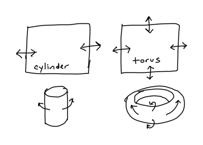
Normally when making an infinitely scrollable game map, we make an infinite game world, procedurally generated as you move around. I wanted to explore making an infinitely scrollable game map for a finite world. The standard ways to do this are:
- Wrap around the east/west sides of the map. This corresponds to a cylinder world.
- Wrap around both the east/west sides and the north/south sides of the map. This corresponds to a torus world.
Both approaches work pretty nicely. I want to explore placing a grid on a sphere world. This is a bit trickier. Try dragging the map around, Google Maps style:
Let’s break this down…
1 Sphere behavior#
This is the behavior I want:
- You can walk west/east and wrap around the map. This is like the cylinder or torus.
- You can walk north/south but you do not wrap around to the other side. This is like cylinder but unlike torus.
- You can walk past the north/south poles and stay at that pole but are facing the south/north instead of north/south. This is unlike cylinder or torus.
- Walking west/east to wrap around the map takes less time near the poles than near the equator, because those paths are shorter. This is unlike cylinder or torus.
I also want to be able to walk to the poles.
2 Flat surfaces#
To turn a sphere into a flat map we need to add 720° of curvature.
The usual way to put tiles on a sphere is to use one of the five Platonic solids[1]: tetrahedron (4 triangles), cube (6 squares), octahedron (8 triangles), dodecahedron (12 pentagons), icosahedron (20 triangles). The vertices of these solids are “singularities” — points that do not behave as expected when flattened out.
| shape | singularities | distortion | tiling | notes |
|---|---|---|---|---|
| tetrahedron | 4 | 180° | square, triangle | easiest to implement? |
| cube | 8 | 90° | square | missing 1 of 4 squares |
| octahedron | 6 | 120° | triangle, hexagon | missing 2 of 6 triangles |
| isocahedron | 12 | 60° | triangle, hexagon | hexagon becomes pentagon |
| dodecahedron | 20 | 36° | none? |
The more singularities there are, the smaller each distortion can be. We get the smallest vertex distortions with dodecahedrons, but we don’t have a nice way to tile their pentagon faces, so we instead use isocahedrons with the triangle faces tiled with hexagons (with 12 pentagons at the singularities).
I like the tetrahedron approach because a single (x,y) coordinate can represent your position on the map. This could be simpler to implement than the other approaches, and it also allows for square tiles. From the map projection world[2] there are a few other systems that also allow for a single (x,y) coordinate. The familiar Mercator, Gall-Peters, and related maps are cylindrical[3] systems. They allow a single (x,y) coordinate, and have two singularities, each 360° at the poles. These don’t give me the behaviors I listed in the previous section, and don’t let you walk over the pole. The Peirce Quincuncial[4] projection puts the entire sphere on a single square, and glues opposite ends of the square together. The Guyuo[5] and Adams[6] projections put the sphere on two squares that are glued together. Gringorten[7] looks interesting too. I’ve not evaluated these yet to see if they give me the behaviors I want.
In my previous explorations for this problem, I tried hexagons on an icosahedron, and then I tried squares in a HEALPix layout. HEALPix is a variant of the cube approach. In implementing it, I decided I should try cubes directly. That’s what I’m doing on this page.
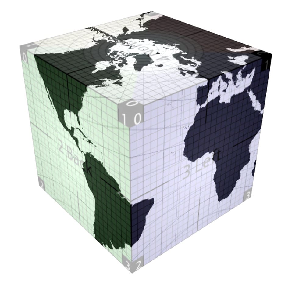
3 Grid on a cube#
Let’s jump right in. Here’s a tile grid on a cube.
There are two separate problems to solve.
- How do we deform the cube into a sphere? I think this is relatively easy but it’s not something I had ever done before so I’m going to describe the steps I took to do it.
- How do we deal with the surface of the cube in terms of coordinates, distances, movement, etc.? I think this is a little harder, but it doesn’t look too bad so far.
These two problems are mostly independent. The first is about the visuals. We want to render the world as a high level map. The second is about the gameplay. We want to be able to move around on a zoomed-in map.
4 Cube to sphere#
This part was surprisingly easy. Consider each face of the cube separately. Consider the face on the right, where x is always +1, and y and z both vary from -1 to +1. Each vertex on this cube has |x| = 1. But for a sphere we want the total distance sqrt(x^2 + y^2 + z^2) = 1. We can normalize the vector (x,y,z) by dividing by its length. I think this is called the gnomonic projection[8].
However…
Look carefully at the morphing. The centers of each face get enlarged a lot more than the edges do. This is an area distortion. In the papers I’ve read, this is measured in terms of maximum distortion (area of largest square divided by area of smallest square), average distortion, and root mean square error. In some papers the distortion is shown visually.
There are several ways to correct for area distortions but each approach introduces other distortions. It’s an optional step so I’ll cover it in the appendix.
5 Cube surface#
The cube is made of six squares. We can unfold the cube to see them:
If you’re standing on a cube face and move to an adjacent face, which face will you end up on?
There are a few different ways to set up a coordinate system. I decided to have a coordinate for the cube face, and then a position within the cube face. I also need an orientation, because when we walk around the pole the screen gets rotated.
For the cube face, I originally had used 0-5 as you can see in the diagrams, but decided to change it to row 0, 1, 2 and a column 0, 1, 2, 3. For rows 0 and 2, I only use column 0. I also have a face orientation of 0=North, 1=East, 2=South, 3=West. With this coordinate system, I needed only three cases for moving from face to face:
- Pole to equator - north/south - from row 0/2 to row 1, orientation becomes column
- Equator to equator - east/west - stay in row 1, +1/-1 to column, orientation stays same
- Equator to pole - north/south - from row 1 to row 0/2, column becomes orientation, column becomes 0
I wrote a formula for each of these separately and then used that to draw the above diagram so that I could make sure all the cases worked correctly. The color coding of the poles helped me spot mismatches. You can see the messy code in square-tiling-of-sphere.js, in the Coordinate class.
The second part of the coordinate system is the position within the cube face. I haven’t built a class for it yet, but look for the Adjust coordinate within a cube face in the code. I’m keeping this coordinate in screen space. When the coordinate falls outside 0 ≤ x ≤ 1, 0 ≤ y ≤ 1, it means we need to move to a different cube face. Then wrap x,y back to the 0-1 square, and rotate (x,y) if necessary based on the orientation of the cube face. I think this is probably not the best way to do things, but it works for this demo, so I’ll revisit this later.
6 Appendix: reducing distortions#
We can reduce the area distortion by using the commonly used “tangent adjustment”. The original morphing from cube to sphere uses equal distance between the grid lines. Instead, we can use equal angle.
Turn the cube into a sphere:
Apply tangent adjustment:
The standard tangent adjustment uses a forward formula to convert cube vertex positions to adjusted positions, which then get morphed into a sphere by dividing by the length of the vector. Given a coordinate w, transform it to π/4 * atan(w).
However, if you are rendering the sphere on a GPU, you might be using texture lookup. In this case, you will have the output position, and want to calculate the original position by using the inverse adjustment in the shader.
Given a transformed coordinate w',
invert the transform to tan(w′ * π). [is this right? check the papers again because it doesn’t match the forward transform]
There are three types of things we want:
- Area - all tiles cover the same area
- Aspect - all tiles have the same width and height
- Angle - all tiles meet at 90° angles
We can’t have it all! As far as I can tell, the only things we can do are change the distortions from one type to another, or move them from one area of the cube to another. The tangent adjustment is one of many approaches and none of them seem obviously “best”. There are lots of different approaches.
I relied on these three papers:
- Zucker, M., & Higashi, Y. (2018): Cube-to-sphere projections for procedural texturing and beyond[9]. Journal of Computer Graphics Techniques Vol 7.2.
- Dimitrijević, A., Lambers, M., & Rančić, D. (2016): Comparison of spherical cube map projections used in planet-sized terrain rendering[10]. Facta Universitatis, Series: Mathematics and Informatics, 31(2), 259-297.
- Lambers, M. (2019): Survey of Cube Mapping Methods in Interactive Computer Graphics[11]. The Visual Computer, 1-9.
The first one in particular is not about the sphere/cube mapping specifically. I had found it while learning about blue noise generation. The paper covers blue noise, voronoi, and sphere/cube, so it’s been a great reference for me to learn about all three topics.
Other papers worth looking at:
- Lu, F., Song, Z., & Fang, X. (2014): Generation of orthogonal curvilinear grids on the sphere surface based on Laplace-Beltrami equations[12]. IOP Conference Series: Earth and Environmental Science (Vol. 19, No. 1, p. 012012). This paper compares gnomoric, tangent, conformal, and elliptic methods for both area and angle distortions. Elliptic looks promising (see Fig 2.4–2.6) but I didn’t figure out how to implement it myself.
Google’s S2 library has compile time options for the tangent method, a quadratic method, and a linear method. By default it uses its quadratic method; see the comments in the code[13] for their tradeoffs.
The literature is full of various types of grids used by different projects. There are always tradeoffs involved. I wanted to implement more of these (especially Algebraic Sigmoid and Nowell’s Method) and compare which ones are best for my needs, but I ran out of time for this one-week project, and I also realized that it’s only for the minimap and it’s not that important right now.
7 Appendix: more#
I don’t remember when I first started thinking about this problem but I did find an old reddit post[14] about someone wanting to run a simulation game on a sphere. In my previous attempts at this problem I collected notes here[15] (2016) and here[16] (2019).
Andrew Willmott has written up notes about Spore’s planetary coordinate system[17], and has shared code too! I didn’t know about this until after I worked on this project.
Someone has built a non-Euclidean rendering engine that produces 3D worlds. At 41 seconds into the video[18], it shows three rooms that come together at a corner, similar to what I’m going for. Thanks to a reader for telling me about this video.
See https://www.bowerbyte.com/posts/blocky-planet/[19] which makes minecraft-like blocky spherical planet
NASA/Goddard developed a version of quadrilateralized spheres for COBE sky maps[20], which supports a recursive subdivision scheme to store data. NASA/JPL developed HEALPix[21], which supports calculate spherical harmonics. NASA/Goddard also developed Finite-Volume Spheres which evolved into NOAA’s FV3[22] for weather simulations, which supports vertical data, a nested grid, and better calculations across cube faces. FV3 was used to upgrade NOAA’s weather forecasts in 2019. Thank you NASA!
The next step for me is to try procedurally constructing a game map on this cube, and then see how it feels to walk around on it. I did that here!